2.4. COMPUTER LOGIC |
As mentioned in a previous Chapter above, the operation of digital computers based on TWO defined physical states:

|
Means that the electronic circuits, which perform various computer operations, behave like switches, and various electronic versions perform operations with states "1" and "0" under the laws of LOGICAL SUGGESTIONS that can be TRUE or FALSE. Can not simultaneously be both.
The basis of this branch of logic, dating back to Aristotle, was processed and virtually defined its symbols mathematician George Boole. According to him, this branch of mathematics (laws truthfulness) called BOOLEAN ALGEBRA, is engaged in the mutual relations of elements in the set and between sets.
SET is a group of elements that have at least one thing in common to a single group of elements (general set). This means that a group of elements can be divided into two sub-groups - subsets as follows:
     1. Subset of elements with common properties ----------- e.g. 'A'
     2. Subset of elements that don't belong to the first --- e.g. 'non A'
This division in the set clearly illustrates the image below.

|
| Figure* 2.4.1 General set of elements / Relations between sets. |
Subsets of the 'A' and 'non A' are complementary, 'A' is represented as TRUE and joins his condition "1", and it is complementary set of 'non A' as FALSE, and was joined by a "0" state. Both conditions as a result of processing, can not coexist. The same is true for a subset of 'B' and 'non B'. It also considers interaction between sets, ie mutual relations between elements of different sets.
Operations that associated above conditions in the set and between sets are:
1. Operation NOT () ---- negation of the existing situation 2. Operation OR (
) ----- requires at least one (+) true condition results in a "1" when processing 3. Operation AND (
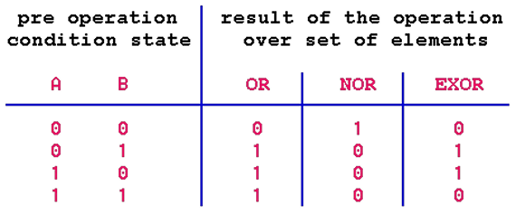
) ---- requires all (×) states to be true result of "1" when processing 4. Operation NOR --------------------- negation OR 5. Operation NAND -------------------- negation AND 6. Operation EXOR ( EXclusive OR ) --- requires only one true state of of result of "1" when processing
The first three operations are basic, while the others were derived from them. The results of the relationship between the sets in the set are displayed TRUTH TABLES as follows.
1. Operation Truth Table for NO:

|
In the left column of the table are entered all possible conditions that set 'A' may have, as well as combinations of all state meetings if there are multiple sets. In the right column, or columns, enter the condition that occurs as a result of cataract surgery or surgery of the display shown in the left column.
2. Operation Truth Table for OR, NOR and EXOR executed over different combinations of elements of two sets.
 |
3. Operation Truth Table for AND and NAND executed over different combinations of elements of two sets.

|
From the table it follows that some operations between sets corresponding operations with binary numbers. If "1" and "0" is not used to denote truth and falsehood, but for the existence and non-existence of pulses, specially designed electronic logic circuits will execute logical operations with the impulses and allow performing arithmetic operations. Therefore, these electronic circuits, typically performed in an integrated technique, called INTEGRATED LOGIC ELECTRONIC CIRCUITS.
When designing logic circuit design, the basic design procedure can be applied to minimize logic circuits, which gives the same required functionality but with a smaller number of basic logic circuits. We should respect the basic laws of Boolean algebra governing the relations between sets, which are:
Sign ' + ' is basically sign ' ![]() ' (and the sign '
' (and the sign ' ![]() ' is used) - UNION, defines the set of all elements that belong to at least one of the sets A or B, therefore elements which belongs to any part of integrated sets.
' is used) - UNION, defines the set of all elements that belong to at least one of the sets A or B, therefore elements which belongs to any part of integrated sets.
Sign ' × ' is basically sign ' ![]() ' (and the sign '
' (and the sign ' ![]() ' is used) - INTERSECTION, defined as the set of all elements that belong to sets A and B, therefore elements which at the same time belong to all of the observed sets.
' is used) - INTERSECTION, defined as the set of all elements that belong to sets A and B, therefore elements which at the same time belong to all of the observed sets.
Accordingly, since the output state of logical operations in a binary system can be "0" or "1", the basic RULES of SIMPLIFYING to be used in logical expressions are:
|
|
Following these principles is easy to prepare and minimize the necessary logical schema, which are the basic logic elements described in the next chapter. What is the minimization? Basically mathematical procedure for respecting these laws sizes given logical function, which describes what will be output depending on the values of the input variables, simplifies and reduces and hence the number of basic logic circuits to be used less. But leave it to professionals, and good to know that is possible.
|
Citing of this page: Radic, Drago. " Informatics Alphabet " Split-Croatia. {Date of access}; https://informatics.buzdo.com/file. Copyright © by Drago Radic. All rights reserved. | Disclaimer |