7.1.1. A/D Converter |
The simplest, A/D converter converts the analog signal into a binary number. Analog-to-Digital converter is not converted into a digital value overall analog signal, but only his sample in time. This is not the actual amount of sample taken, but the value is taken to the closest level available at the time of sampling. Number of levels depends on the number of bits to be used for the binary number in the conversion process. What levels are denser, the conversion is accurate, and necessary number of bits in a binary number is higher. The principle of sampling is shown in Figure 7.1.1.

|
| Figure 7.1.1 Sampling of analog signal in time. |
During the time of sampling electronic assemblies transducers analyze what is the value closest to the actual level of the analog signal at that point. Established value levels be remembered by the next sampling must be converted into binary form, and the binary value of the program to deliver the same support that will be stored in a computer's memory or to a file on the hard drive and usually graphically display the current process on the computer. So, a good deal of action has to be done during the conversion. Time of sampling manifold is shorter than the sampling period (sampling frequency). If the sampling frequency is higher then conversion is quality.
Examples in the Figure 7.1.1 shows that for conversion of analogue signals is selected eight (8) different levels that will be timed to follow its changes. The eight levels can be displayed with binary combinations of three (3) bits. The accuracy of such a system would be insufficient for quality monitoring changes analogue music signal or temperature differences throughout the year in some climates, but would say, was sufficient to monitor spending galvanic cell during operation in respect assess its usability.
The sampling procedure does not take the actual resolution of the analog signal, but the closest possible of the available levels. Part of the message is LOST. The loss is lower when the available number of sampling levels higher and higher sampling frequency. This continuous process of converting the analog signal into discontinuous values is called QUANTIZATION. Rounding the real value of the analog signal quantization in a higher or lower value by default levels of noise that occurs is called quantization NOICE. The choice between the quality and the real need to be used in the practical application parameters adequate to the task of satisfying the needs of users. Thus, a large number of samples per unit of time and a multi-level sampling error lower than the actual value of the analog signal conversion is better. Deviation recovered digital signal and the reconstructed analog signal based on the digital recording compared to the original analog signal causing the so-called NOICE of QUANTIZATION.
Samples of the analog signal, converted into a binary number between two samplings, sent mostly by bus or PC via the parallel port in the form of parallel transfer of digital computers, which are then processed. What is a short conversion time of the A/D converter works faster and is its most significant feature. Sampling results can be stored on a computer in the form of plain text files or files of a complex content such as music. Example of sampling music signal is well illustrated by Figure 2.3d.
Example I
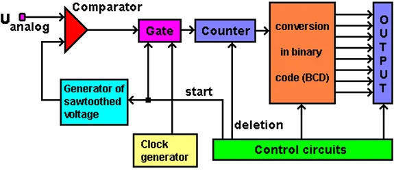
A/D converter based on the principle of comparing the observed input signal with known sawtooth signal is one of the simplest way.

|
|
| Figure 7.1.2 A/D converter with comparator of signals. |
The control section provides a sampling clock and giving the order to delete the old content and start reading sawtoothed voltage generator. At the same time opens the door through which the pulses from the counter generator clock. Counter counts pulses until the moment when the size of the analog mode is equal to the size of sawtoothed voltage. Comparator then gives the order to stop the door from the passage of the clock generator counter. When the sawtooth voltage reaches a maximum value controllers give the order to read the contents of the converter counters and on the basis that deliver the output of the corresponding binary combination and then the whole process repeats.
To properly work of A/D converter the size of observed analog signal (voltage) must not exceed the maximum value sawtoothed voltage.
According to the principle of operation described it is clear that the sample while enumerating always be less than the actual value of the input analog voltage, because counting stops at the moment of equalization sawtoothed and measured voltage.
Better results are obtained when the generator instead of sawtoothed voltage, generator used sukscesivne approximations. Input voltage is constantly compared with the output voltage calculated based on the value of the counter. Logic controller will be reduced by either increasing the value of the converted output voltage until it finds the minimum difference between the counter values (sample) and the actual value of the input voltage. Comparison then stops and score counter is converted into binary code. It is possible that the sample is greater than the input value if the error when compared with the values of discrete levels lower.
Examples in the Figure 7.1.2 is the only one of the subsystems of the overall performance of the A/D converter. With him there are several subsystems that enable the transducer in the computer, which will be further described.
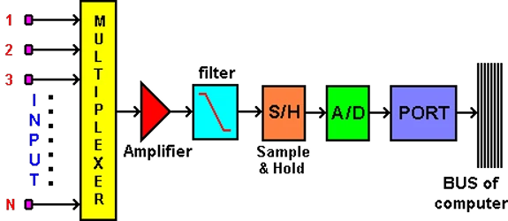
It's good to use the system that allows the measurement of multiple processes so that each of them provide some time to read the input values, and that time monitors processes one after another continuously (time division multiple access). For each measurement process provides a discrete period of time for its follow-up, then a multichannel measurement system.

|
|
| Figure 7.1.3 Multi-channel measuring with subsystems. |
Multiplexer allows to at regular intervals provide discreet monitoring of all physical quantities at the entrance. Sub-components following the multiplexer with the following tasks:
For the measurement of physical quantities using the A/D measurement system is good to use the multichannel measurements to monitor multiple parameters. Computer program and its support is absolutely irrelevant to analyze one or more groups of data, as they are today without specific demands enabling their performance. To analyze and display data ensures software.
The flexibility of multi-channel system can be seen in the number of multiplexed inputs and the quality of how individual devices are implemented, before or after the multiplexer. In fact it would be good to each branch has its own four above mentioned subsystems. Of course this increases the cost of multiple transducers but allows far greater control over the processes that are monitored.
|
Citing of this page: Radic, Drago. " Informatics Alphabet " Split-Croatia. {Date of access}; https://informatics.buzdo.com/file. Copyright © by Drago Radic. All rights reserved. | Disclaimer |