1.3. THEORY OF SIGNAL |
Signal, any kind, is designed to be a convenient way to deliver some messages to the destination. In the area of communications, signal processing, and in electrical engineering in general, a signal is any time or change of state of the media through which it spreads. In computer technology is reflected primarily in changes of electrical quantities that are transmitted through the computer system. Signal transfer messages from a source to a destination can be basically done in two ways:
Every transfer through the high-frequency communications system, the signal is experiencing change, which is the source of the goal to be in it 'pushed' message and the destination of it 'took'. This means that in some way be affected by the change of the parameters of a high-frequency (amplitude, frequency or phase) and know how to interpret. The process of signal processing in the submission with which the high-frequency signal transmission - having a 'imprinted' low frequency (NF) message signal is called MODULATION. On the receiving side the reverse process takes place, called DEMODULATION.
Whatever changes the signal experienced, mathematical analysis, i.e. the development of Fourier's order, it will show that it is essentially composed of a series of 'sine' components, each of which has its own parameters, which summed together give the final shape of the signal. So, to be processed signal, or better said composite signal, transmitted through a communication channel must be transferred to all its components individually 'sinus' nature.
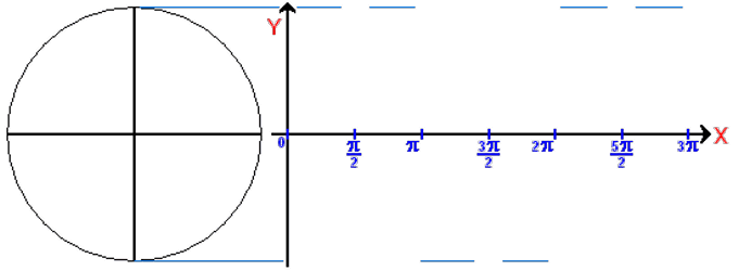
Creation of sinusoidal signal is shown in Figure 1.3.1.

|
| Figure * 1.3.1 Generating sinusoidal signal. |
If we observe the rotation vectors (phasors) size ' A ', which turns at a constant speed, and monitor what his top 'writes' in a rectangular coordinate system, they will get a curve which is the functional dependence:
y(x) = A • sin (x)
For ease of discussion A = 1, and y(x) = sin(x). ' x ' is the value of traversed angle that vector ' A ' made during the rotation. But speed was not the same. In order to obtain time-turning experience vector is defined angular velocity ' ω ' that says how fast vector describing a full circle of 360° (2•π).
ω = (2•π) / T
Time ' T ' is the time required for a vector describing a full circle (period), and the number of cycles (periods) in one second is the frequency of repetition of the cycle f = 1/T, and is analogous to ' ω ' called the ANGULAR FREQUENCY. Instead of undertaking and the angle on the abscissa coordinate system can be observed during the time ' t ' or repetition frequency phenomena ' f ' (hereafter just frequency), then the time and frequency display. Time view of sinusoids by substitution of x = ((2•π)/T)•t = (2•π•f)•t, and at the abscissa instead angles (0, π/2, π, 3π/2 ...) indicate the time (ms, s, min, hours ...), and this view is the TIME DOMAIN.

|
The above formula defines the flow of sinusoidal functions or sinusoidal signals in some settings (power, lighting, sound ...). In signal processing can basically affect change its amplitude, frequency and phase. If these changes are consistent with the message signal for the MODULATION process, and the 'read' status change is proceeding DEMODULATION. The basic requirement in order to effectively achieve the specified signal that message has a much lower frequency of the transmission signal - holders. How to influence the different parameters of the signal carrying the message hence the different names and acronyms for different types of modulation-demodulation. The basic types are:
The following Figure shows the low-frequency message signal, high-frequency carrier signal and the resultant modulated signal in time and frequency domain. When the frequency changes are also happening and changing phase modulation and the result is similar, but the design of electronic circuits and entrusted depends who will oversee the VF signal.
 |
| Figure 1.3.2 AM and FM / PH modulated signals in the time and frequency domain. |
The result is that the modulation is around supporting high-frequency generating a high-frequency side components basically include a message, and in which the modulation frequency can be more. Number of lateral components increases if the NF signal message is not sinusoidal form as the previous Figure, but is analogous to say (according to Figure 1.1.2) or rectangular and can be broken down into a series of low-frequency harmonic components, as in Figure 1.3.5 for the angular signal. Then for them popularly used term 'sidebands'.
Signal any form is composed of sinusoidal components of different amplitudes and frequencies. Regardless of whether the low-frequency, high-frequency or modulated signal, all the sinusoidal components of which are considered signal composed called the signal SPECTRUM, which is essentially the frequency range from minimum to maximum frequency components which are considered signals. When transmitting the modulated signal is transmitted all or part of the frequency spectrum and resulting in some versions of the transmission through the communication channel transmits only one side of the belt without VF bearing signal, which is then regenerated in the process of admission (SSB - Single-sideband transmission). Frequency spectrum required for signal transmission time is smaller and on this issue the necessary communication channel is 'narrow'. See in the Figure that the change of amplitude AM signals, because of the influence of the surrounding noise, thunder, for example, can lead to an incorrect entry in playback, while the frequency or phase modulated HF signal more resistant to such interference.
In the last decade of the last millennium typically the transmission TV messages, using an amplitude-modulated high-frequency signal to transmit images and frequency modulated high-frequency signal for voice transmission. Both signals are arranged frequently occupied area called 'CHANNEL'. Different channels used various high-frequency signals-holders in order to avoid another 'mixed'. The reason for using high-frequency carrier signal as the signal message is due to a more efficient propagation as electromagnetic waves, which in general is not particularity signal messages. How did they change the signals in accordance with the changes dictated by the message this kind of message transmission technology falls into the analog transmission signal modulation. Application of analog modulation in computer technology is not widespread, but it is present (such as a modem or DVB), and shall not be subject to further discussion.
Digital message is a digital electrical signal. It is a signal that consists of DISCRETE states of amplitude, precisely defined size of the different amplitudes of signal. The simplest use of discretion is when voltage of signal is present or absent and does not matter how big is the size of signal amplitude, which is essentially the basis of the work of digital communication systems. It is only the presence in the form of a positive or negative current output of the transmitter and the recognition of this condition (no forms) in the receiver. In most cases it is symbolically marked with a "1" and "0". This electrical signal may be transmitted directly to the way that it is as different voltage levels (only two) send over some physical water to the receiver, which is usually in computer technology. Another way is to make him modulation signal sinusoidal form which is then sent to a physical medium (guide) or clearance (radio waves).
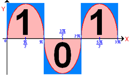
If we take a sequence 101010101 can be easily observed similarity with sinusoidal signal. Amplitude is irrelevant from the point of the message, but the frequency of interest. What is the frequency exceeds this means that over the period of time can be transmitted over a "1" and "0", or more message-information.
 |
|
| Figure 1.3.3 Frequency according to sample 1010101... |
According to Figure 1.3.3 could be concluded that the sine wave signal can convey the message type 101010101..., but if the message type 1111000011110000..., duration of pulses, as a group composed of four separate pulse increases and the frequency decreases and if you say the shape 110000001100000011000000... changing the duration of positive pulse, negative pulse duration and frequency is not uniquely determined more by Fourier analysis of this complex signal consisting of multiple sinusoidal signals of different amplitudes and frequencies.
Mathematical analysis of the signal to the Figure 1.3.3 would show that it consists of the fundamental frequency sinusoidal signal ' f ' and a series of small signal and larger in amplitude by frequency (harmonic components) as illustrated in Figure 1.3.4 animation but only for two harmonic components.

|
|
| Figure* 1.3.4 Composition of rectangular pulse. |
The theory says that rectangular pulses contain a large number of harmonic components and occupy that frequency range is very wide (theoretically - infinite). The practice is thought to signal a form of 'almost' original (rectangular) if the transmitter to the receiver transmits the first seven harmonic components. Equation, which in Fourier's series expansion, describes a rectangular signal and its components is:

|
If n = 1 this is a primary component amplitude sinus [4/π]•[1/(2•n-1)] = 4/π and the frequency f•(2•n-1)] = f , for n = 2 is obtained by the amplitude component [4/π]•[1/(2•2-1)] = 4/(3•π) and the frequency f•(2•2-1)] = 3•f, for n = 3 harmonic has amplitude 4/(5•π) and frequency of 5•f, and the next harmonic amplitudes 4/(7•π) and the frequency of 7•f so on to infinity.
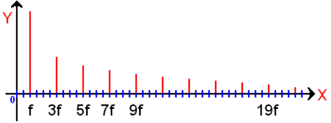
The individual components of a rectangular signal (harmonics) with a frequency that is just odd multiple of, i.e. discrete values of frequency and amplitude which basically fall in the pattern sin(x)/x , which indicates that the variable size and phase. The individual components can be displayed in a different manner than the picture 1.3.4. If the abscissa set frequency ' f ' and on the ordinate the amplitude of each component will receive the signal frequency spectrum, and its display is called the FREQUENCY DOMAIN.

|
| Figure 1.3.5 Harmonic amplitudes of rectangular pulse. |
The picture shows that the tenth harmonic frequency 19•f, has drawn a greater amplitude than it should be drawn by the tested scale, but it can be concluded that the amplitude of harmonics with higher frequencies rapidly declining and that their part in shaping the signal becomes smaller. But in practice it is not possible to transfer the entire frequency spectrum of rectangular pulses. Consciously going to the rejection of components that are less than half the amplitude of the main signal. Dropping the higher harmonic components causing the distortion, but modern electronics knows various methods of analysis very successfully identify what sort of impulse works. According to Figure 1.3.4 for two harmonics in addition to the signal give a satisfactory result. It is evident in this 'resistance' digital system, because their shape is not important impulse for its detection, as different methods of comparison (correlation) between the received pulse and rectangular template very efficiently achieved with almost insignificant losses.
Signal transmission type 1010101 ... The situation is the most challenging because it has the highest frequency, compared to something like ... 000111000111 or the like, and is usually enough to get away from the receiver to the destination transfer all components whose frequencies up to a limit of approximately fg=1.6 • fmax. The cutoff frequency is defined bandwidth and CHANNEL necessary for the realization of data transfer. Therefore, can not be passed even the first harmonic of the signal that would have the highest possible frequency.
What would the frequency domain components had sine signal? One course. Signal of large amplitude and narrow-spectrum usually is some brief annoyance of great power, and if he cares about is present can be easily isolated. But the presence of a range of frequencies within a frequency range (spectrum) with random changes in amplitude and frequency, called the noise, and it can very effectively disrupt communication. The quality of communication is apparent precisely how much is resistant to its own generated noise and the external noise.
The range of frequencies that must miss most is if the pulse duration is less (f = 1 / T), which means that for shorter pulses using a larger frequency range, which pushes the technological criteria that communications equipment must satisfy (kinds of portable media, mode of delivery and admission, etc.). The ability of a computer communication system that transmits a certain amount of data per unit of time describing his physical power and is called the BANDWIDTH (BW), which is measured in bps (bits per second). So today we meet with sizes like 64 kbps, 128 kbps, 64/128 kbps for dial-up communications, and sizes 10 Mbps, 100 Mbps and 1000 Mbps and for the local computer network of institutions in the enterprise. So BW has nothing to do with the speed of data transmission, but with the amount. Analogous to the above description would fit a small street and highway. Vehicles are in both cases at the same speed, but their number is on the road and therefore different amounts of vehicles that pass by time.
But it is not, from the standpoint of the user what he can fully take advantage, especially if the system is shared with others (computer network). Part that the user can make the available bandwidth is called THROUGHPUT (TP) and depends on various conditions, such as number of active users on the network, the type of data being transferred, device type and other.
So if you know how a file is large (as it has a bit) and if you know what is available BW (theoretically 56 kbps modem) can be calculated how long it takes to transmit data from one location to another.

|
S - File size (bits) BW - Throughput capacity of the channel (bps) T - Time required for the transfer (s) |
Of course, in practice it is impossible to use the entire BW, especially if it is shared by more users. Then the bandwidth for each user account with TP instead of BW. Unlimited amount of bits can be sent over the communication channel, just a matter of how much time it takes. What is more bandwidth can take less time. If it is possible to transmit enough bits to transmit images of a size of 25 times per second, that's the image transfer in real time. If BW is too small can be any time to collect images and then display, but it is not communication in real time. First, it would be some kind of video conferencing directly, and another individual participants report video conferencing gather all the necessary bits. For TV signal (analog) this is not possible. If there is no available bandwidth there is no transmission.
SUMMARY:
It has already been pointed out that the transmission of messages carried on the way to some kind of combination pulse adds some meaning. In order for the receiver and transmitter know 'discuss' the meaning of these combinations must be the same to them. Diversity in solving this problem almost led to confusion in the communication between systems from different manufacturers. Therefore, at the level of the whole community (or rather the world) set up various institutions to which the concerns that accompany the current situation, recommend or impose standards and provide guidelines for new technology. Who does not care recommendations or standards is not competitive.
Each composite signal is composed of many sinusoidal signals, basic components and harmonic components of the crowd, especially the rectangular signal. If you make it through the communications channel transmit all content signal frequency range in the frequency domain would be very large and technically unacceptable. Therefore deliberately limited frequency range (scope) that is passed to the detriment of quality, mainly to the extent that meets user needs. Narrowing the frequency range that is used to transmit signals inevitably leads to distortion, but modern electronic circuits with its logic and analytical methods for correcting errors can largely annul the effect of these limitations.
Another feature of the signal, regardless of its nature is to signal messages, mostly low frequency, very low spreads as an electromagnetic wave through space, while the high-frequency signal propagation by regarding both significantly more effective. Therefore, the different procedures modulation signal message injected into high-frequency wave - holder, by modifying any of the parameters of high-frequency signals in accordance with changes in the signal message regardless of whether the signal is analog or digital message. Digitizing Signal messages increases resistance to interference, allows use of lower frequency range and time-division multiple access (TDMA), but compared to the analog input signal is aware of the loss of credibility during the transmission range of the level of digitalization. Everything essentially boils down to the requirement that the described procedures must be done in such a way that the average user does not see some significant difference between the transmission of analogue and digital signal messages.
However, as already noted, the message contained in the combination of pulses, symbolically written as 01010101, 00110011 or 10000001, leads us to conclude that this combination of numbers are substantial in modern computer systems. Therefore, we need to extend the established mathematical horizons, and learn to use the binary, octal, and hexadecimal numbers decade and different ways of interpreting and applying individual. The process of converting typed characters into binary string that travels the world to a specific destination, where the reverse procedure turns into something more meaningful, the simplest interpretation of computer systems, and thus forward in computing in the next Chapter.
|
Citing of this page: Radic, Drago. " Informatics Alphabet " Split-Croatia. {Date of access}; https://informatics.buzdo.com/file. Copyright © by Drago Radic. All rights reserved. | Disclaimer |