UTP, STP communication cable |
Using a coaxial cable has a major drawback in the fact that the broken cable leading to the termination of the entire functionality of the network. It is entirely supplanted the use of the copper pair, which is standard in the development of this type of connection experienced a good deal of revision and is constantly evolving. Today in use for connecting wiring using cables with 4 twisted pairs (8 wires) to carry the signal. As used four pairs this means that using this type of cable can achieve full-duplex communication. The basic purpose is to connect network interface card (NIC) of the computer or other device to the network devices and interconnect network devices themselves. Basically there are two ways the performance of this cable:
In both types of cable arrangement connecting the cable to the connector pair is the same. The primary difference is in the construction of cable and associated communications elements of a shielded cable with a more complex and therefore more expensive. The peculiarity of UTP is low cost and easy installation, which significantly reduces the cost of labor and additional equipment. In addition developed in particularly simple tools to connect this cable to the appropriate terminals and connectors. Connector that uses labeled RJ45 (Registered Jack - recommended plug) and is described in the ISO standard 8877. Slightly larger than a RJ11 connector which is used for the standard double-core and four-core telephone connections. This does not mean that STP cable should be avoided. On the contrary, in environments with high electromagnetic interference or when networking in older buildings, where the proximity to the source of interference can not be avoided, its use is recommended.
Example I
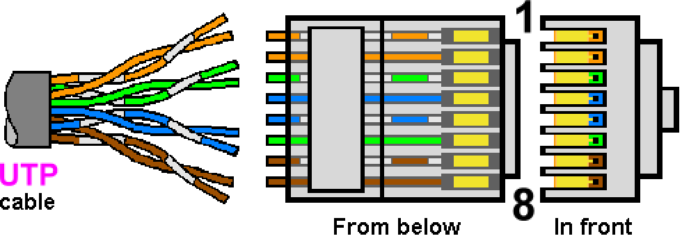
Connecting unshielded UTP cable for the ISDN LAN port RJ45 plug according to 'TIA/EIA 568' standard of wiring.
|
| Figure**** 3.6.18 Connecting UTP cable / RJ45 & Coupler / Tool. ( + / - ) |
Sketch a picture with cable unshielded cable category 5 (five) - CAT5. It consists of four separate twisted pairs that are twisted together again. The colors are standardized. Cable category 1 (one) no twisted pairs. Other categories are in quality between these two, or better. Twisted pair cable wire resistance increases the influence of external disturbances. Way - the wiring diagram's pin RJ45 connector (pinout) with the cable is not in ascending order according to colors at image 3.6.18 drawn on the basis of 'TIA/EIA 568B Wiring' standard that is characteristic of Ethernet communication, as opposed to 'TIA/EIA 568A Wiring' standard that is characteristic of ISDN communications. When crimping the cable to the RJ45 connector, remove the shild around the pairs for about twenty millimeters, sort pairs according to standard, hard to hold the twisted pairs, align them then cut with a cutter on a tool at length of 10-12 mm, plug cable it into the connector and crimp it as shown in Figure 3.6.18e. Communication is the 'TIA/EIA 568B Wiring' standard with respect to dedicate different pairs of lines (twisted pair) cable is under the table:
| PIN RJ45 | ISDN | 10base-T | 100base-T4 | |
| 1 | Power 3 | TxData + | TxData 1+ | |
| 2 | TxData - | TxData 1- | ||
| 3 | TE - NT + | RxData + | RxData 2+ | |
| 4 | NT - TE + | Phone A | BI_Data 3+ | |
| 5 | NT - TE - | Phone B | BI_Data 3- | |
| 6 | TE - NT - | RxData - | RxData 2- | |
| 7 | Power 2 | Unused | BI_Data 4+ | |
| 8 | BI_Data 4- | |||
RX (receive) and TX (transmit) in 10Base-T cabling used one pair for receiving and one for transmitting data. Since these are two separate one-channel means that supported full-duplex operation if the devices that connect possible. Standard across the blue pair allows the simultaneous use of a standard telephone channels. T4 cabling does not use specific registers for receiving and transmitting, or 2 pairs are accurately determined (RX and TX pairs) as a one-way, work compatibility with 10Base-T, and two-way (bi-directional), of which three pairs are used for data and the fourth for the establishment of the collision. ISDN data as a separate category, is listed for illustration only.
Usual standard RJ45 connector to connect the UTP cable means that the schedule pair cable to the connector pins at both end the same. This is primarily used to connect the network interface card (NIC) workstations for access network devices like a hub or switch. Network interface card (NIC) connected to the network device over multiple joints. First, the shorter cable (cable outlet) NIC connects to the wall outlet, which has one or more ports as a coupler. Jack the network divorce UTP / STP cable connects to the patch panel in the switching cabinet (rack) in which the network devices. Socket connection panels are shorter cable (patch cord) connects to the appropriate network device. The total length of these segments of the NIC to a network device, usually an access switch, shall not exceed 100 m, although it is recommended that the total length of connected cables to be 5-10% lower because of possible losses at the joints. Stated best illustrated Figure 7.5.2. Hence, network devices are designed to function properly with cable lengths up to 100 m, taking into account the total length of all the cables from the computer's network card to the terminal in the network device, This means that in case of need, two shorter cable can be connected using a coupler shown in Figure 3.6.18c, respecting the limits of 100 m.
Of course, to connect the UTP connector on the cable must have tool. At the animated Figure 3.6.18d are shown simple crimping tool (connection cable plug), that have cable cutter and stripper and docking-slot for UTP and PTT connectors regarding to injecting connector pins into the cable wires. Displayed pliers are only part of a set of tools which is used by professionals, but for home use at a price affordable and quite satisfactory considering the basic maintenance of home local network.
Network HUBs and SWITCHes devices have such a schedule on this pin sockets to outbound traffic on this pin with the NIC comes to receiving PINs of HUB and vice versa (full-duplex). When the same type of devices connect, or devices of the same OSI layer, for example, connection from HUB to SWITCH, then a crossover cable is used, which is peculiar to that on one of the ends of the receiving and transmitting PINs to RJ45 plug swap places. If the connection is a 'slave' the 'master', this connection is called UPLINK (connection to the master). Whether to apply standard or crossed cable for connection depends on the type of master. Streamlined network devices have the ability to do automatic selection methods on the connectors so that no matter whether it comes standard (straight through) or a crossover cable. Some models have the ability to plug one of the devices (uplink) with a switch to change the pin's schedule.
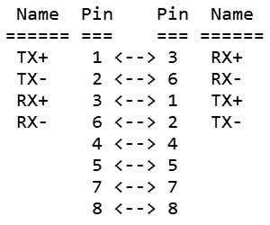
If on the other hand using only two computers that are not too far away, they can get their network cards directly interconnect with the 'crossed' RJ45 connectors (crossover cable - CO) so that pairs of UTP cable directly connecting the output of a computer network card with an entrance to another in order to show the following rules for 10Base-T and 100Base-T4.
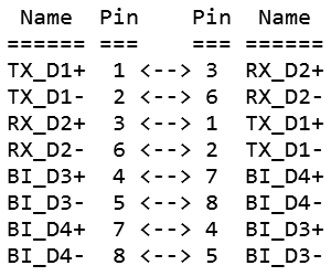
General connection method of transmitting and receiving signal pin's (pinout) for direct computer connection (crossover) for 10Base-T and 100Base-T4 standard display scheme:
|
|
|
Linking pair communication cable and RJ45 connectors directly connected computers (crossover) for 10Base-T and 100Base-T communication with 'TIA/EIA 568B Wiring' standard is as follows:
| PIN RJ45 | 10base-T | 10base-T (CO) | PIN RJ45 (CO) | ||
| 1 | TxData + | RxData + | 1 | ||
| 2 | TxData - | RxData - | 2 | ||
| 3 | RxData + | TxData + | 3 | ||
| 4 | Unused | 4 | |||
| 5 | 5 | ||||
| 6 | RxData - | TxData - | 6 | ||
| 7 | Unused | 7 | |||
| 8 | 8 | ||||
Pairs with PINs 4-5 and 7-8 for 10Base-T and 100Base-T can be connected directly without crossing, because they are not used in the communication, which is not in accordance with T4 standard for 100Base-T4. If you can not use devices that require T4 standard will not be a problem in the communication between devices. How to identify the device used communications standard T4? Simply, one should read his instructions! Communication standard 1000Base-T uses all four cable pairs for simultaneous transmission in both directions through the use of adaptive equalization and a 5-level pulse amplitude modulation (PAM-5) technique as shown in the following table.
| Symbol | 000 | 001 | 010 | 011 | 100 | 101 | 110 | 111 |
| Line signal level | 0 | +1 | +2 | -1 | 0 | +1 | -2 | -1 |
Signs ' ± ' means an increase or decrease in signal level to the previous level. Each of the amplitudes represented 3-bit combination, called SYMBOL. It is a transfer of similar symbols modulation for DVB systems. Similar used 100Base-T2 standard. Standard 100Base-T2 and 100BaseT4 are obsolete and under 100BaseT imply a 100Base-TX standrad which basically requires category C5e cables. 1000Base-TX is a simplified standard that using two pairs for communication.
Linking pair communication cable and RJ45 connectors directly connected (crossover) for 100Base-T4 communication towards 'TIA/EIA 568B Wiring' standard:
| PIN RJ45 | 100base-T4 | 100base-T4 (CO) | PIN RJ45 (CO) | ||
| 1 | TxData 1+ | RxData 2+ | 1 | ||
| 2 | TxData 1- | RxData 2- | 2 | ||
| 3 | RxData 2+ | TxData 1+ | 3 | ||
| 4 | BI_Data 3+ | BI_Data 4+ | 4 | ||
| 5 | BI_Data 3- | BI_Data 4- | 5 | ||
| 6 | RxData 2- | TxData 1- | 6 | ||
| 7 | BI_Data 4+ | BI_Data 3+ | 7 | ||
| 8 | BI_Data 4- | BI_Data 3- | 8 | ||
In all cases the maximum allowable cable length is 100 m, although this distance is not recommended for the 'crossed' to do, because there is no HUM (or switch) to bring about some kind of amplification stable communication. Displayed scheme described for 10Base-T and 100Base-T, with different categories of UTP cable used to connect devices. In the first case it is a C3, C4 or C5, in the second case it is a C5 or C5E, in the third case, it is a C6. Will it be 'crossed' or not depends on which devices are connected. Simply put, the devices of different families are connected with a cable of the same orientation (straith-through) as the NIC-HUB or HUB-ROUTER, and devices of the same family are associated with the 'crossed' cable (crossover) as the two NIC or two HUB. Category cable depends on the speed of data transfer and the criteria are tightened as speed increased.
100Base-T4 standard is designed to allow higher speeds on an already existing older infrastructure which categories of UTP cables, 3, 4 or 5. But modern technology is receiving and transmitting equipment switches and network adapters are enabled to develop standards 100Base-T and 1000Base-TX, which uses only two wires (orange and green) as 10Base-T, and continue for 100 m distance from the switch to users with unshielded UTP cable. No cables must be at least Category 5e (CAT5e-C5e) for 100Base-T, which is actually enhanced category 5, which deprives users concerns about interference and allows full-duplex traffic. 1000Base-TX standard require C6 cable category.
Circuits are presented according to the characteristic of cabling schemes for cable category C5e and C6 and their associated equipment. 'TIA/EIA 568A Wiring' standard specification for the original circuits to C5 category cable, inherited from ISDN systems, and rapid evident difference is that the orange and green pair have been replaced during the merger of the RJ45 connector if it is viewed Figure 3.6. 18th With regard to the principles of communication stated no importance as communication wires in the cable physically the same except for the different colored, but the cables of different categories have the same characteristics regarding the usable bandwidth. But in one environment cabling must be done in the same way without interference standards as recommended for certain categories of cable and related equipment, and for the connection to recognize categories of cables and equipment is USED. Since both the communication patterns, generally correct, there will be no problems if the ' B ' standard used to connect devices in the older and slower equipment, but there will be a communication problem between the device if it is to connect them using a cable that is lower than the required categories because of the different electrical characteristics of individual categories of cable. By way associated pair cables and connectors can be immediately established whether the cable match the defined dedicate them or not.
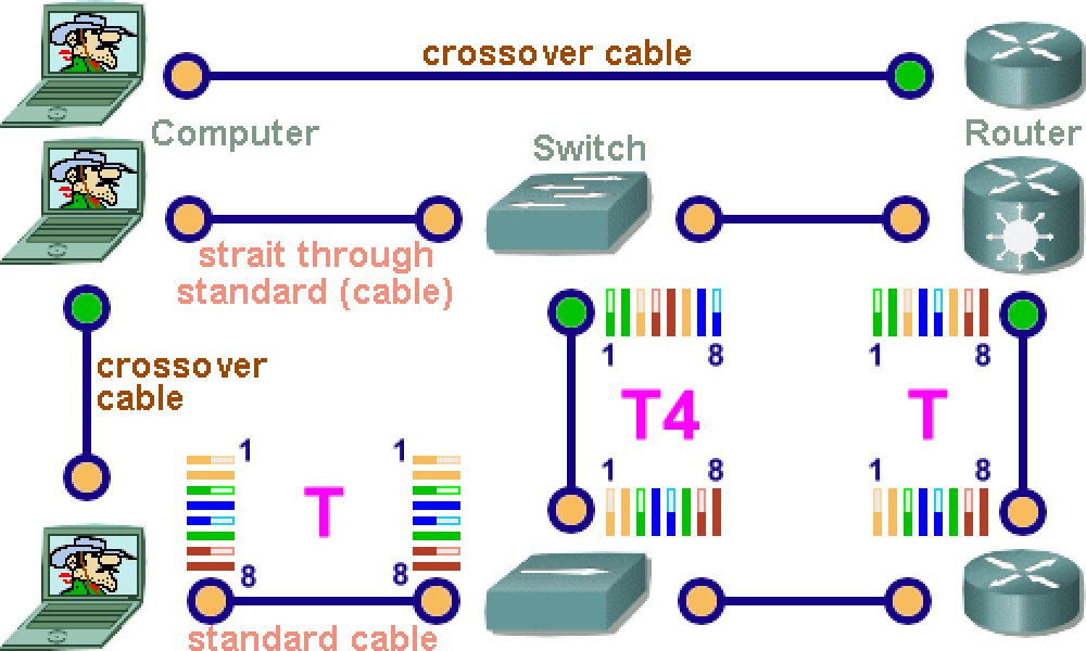
Some of the possible ways to connect computers and network devices, or network devices themselves in a patch (network) closet, and the scheduling pin this on some connectors UTP cable to the 'TIA/EIA 568B Wiring' standards, illustrated in Figure 3.6.19a.
|
| Figure* 3.6.19 Connect network devices UTP cable / STP-C7. ( + / - ) |
If the network devices were used with connections AUTOSENSE type, or that such devices have electronics that automatically detects whether it is connected to a standard or crossed cable and adjusts communication, then you probably are not concerned devices using standard T4 connecting pin in the cable's . Basically all of today's devices have this peculiarity and T4 standard is not implemented in such devices. You are almost no longer used the possibility to connect the phone to pins 4-5 as VoIP (Voice over TCP / IP), voice communication mechanism used to convert analog signals to digital and its further distribution of the principles of computer standards. The principle of structured cabling, which is based on the use of the same communication cable in various applications with different protocols, it does not. Schedule this pin connectors on the cable ends for different ways to connect network devices is shown by Figure 3.6.18a.
Example II
Chronological sequence and properties of certain categories of UTP cable, the approximate representation of more than 50% of new network systems (not by year of publication and the establishment of standards), would be:
| Category | Year | Speed (Mbps) |
Frequency (MHz) |
Curlicues at 1m |
Usage |
| C1 | <1983 | < 1 | 1 | 0 | telephony and ISDN |
| C2 | 1983 | 4 | 10 | 2 - 3 | telephony and ISDN |
| C3 | 1993 | 100 | 16 | 3 - 4 | ISDN, 4 Mbps TR, 10base-T, 100base-T4 |
| C4 | 1994 | 100 | 20 | 15 - 17 | ISDN, 16 Mbps TR, 10base-T, 100base-T4 |
| C5 | 1998 | 100 | 100 | 24 - 25 | ATM, TR, 10base-T to 100base-T |
| C5e | 1999 | 1000 | 350 | 24 - 25 | ATM, TR, 10base-T to 1000base-T |
| C6 | 2004 | 1000 | 200 - 550 | > 25 | ATM, TR, 10base-T to 1000base-T |
| C6a | 2009 | 10000 | 500 | > 25* | ATM, TR, 10base-T to 10Gbase-T |
| C7 | 2010 | 10000 | 600 - 1000 | > 25** | STP (non RJ-style) or RJ45 - 10base-T to 10Gbase-T |
| C8 | 2016 | 40000 | 2000 | Flat | STP, 10base-T do 25Gbase-T / 40Gbase-T up to 30 m |
|
* Cable category C6a has a slightly convoluted plastic core, cross-section, for better separation pair, who are of course each of them curled. He acts as if the cable C5E categories connects to circuits lower categories, so backward compatibility is preserved. When crimping, this plastic guide should be cut off in the plane with a protective shield.
** Cable category C7 is a shielded cable in which some conductive foil shielded twisted pairs and entire cable conductive netting - S/STP. Each pair can be special connectors to connect in a way that benefits each pair separately (analog phone) or two wires together (Internet or VoIP) or to join the pair cable for CATV (cable TV). So, patch panel and the wall socket (outlet) is more complex compared to the RJ45 standard, but also versatile. Connectors are different in accordance with the purpose and supported by the simultaneous operation of multiple simultaneous applications through the same cable but different pair, as shown in Figure 3.6.19b. |
The higher the category of copper cable the greater the demands on the resistance to interference and crosstalk between each pair. But an increasing share of the communications with optical and wireless systems. But the transmission of signals over copper lines still remains a reference for dealing with basic access to the user. It can be expected that from the standpoint of cost, installation, and security prevail use cable with copper wires.
Cat7 cable can be used at traditional way. Cat7 is the abbreviation of Category 7 cable. Cat7 cable has higher bandwidth and faster data transmission speed. Cat7 cable features four shielded wire pairs and the cable itself is also shielded, which can effectively eliminate crosstalk and reduce noise. Cat7 supports the transmission speed of 10 Gbps at a frequency of 600 MHz. Cat7 is backward compatible with Cat6a, Cat6, Cat5e, and Cat5 cables. Since the pairs of wires are shielded, and the entire cable is completely shielded, can be made as rounded or flat cable. RJ45 connector is almost the same, but have the possibility for the wires to pass through the front interface and the excess wire to be cut off afterwards, which makes crimping easier. All four pairs are used for communication. This cable belongs to the group of SF/FTP (Shielded with Foiled Twisted Pair) cables. Has both an overall braid shield and foil shield, with individually foil tape screened twisted pairs.
Cat8 is the latest standard and represents the pinnacle of speed and bandwidth, supporting high speeds of up to 40 Gbps, but over shorter distances of up to 30 meters. This is a cable designed for professional networks and data centers, where speed, stability and low latency are an absolute priority. Although Cat8 is still a rarity in everyday applications, in the world of highly specialized IT networks, it is used to directly connect network equipment. The interesting thing is that after 30 meters, the Cat8 cable specifications drop to 10 Gbps, so it behaves like a Cat6a version of the cable.
SUMMARY:
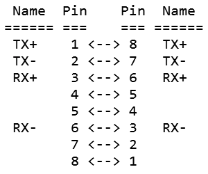
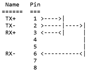
Describes ways to connect RJ45 port for UTP cable is the most common and is primarily related to the communication link between access network devices and computers. A special cable, which is mainly used to connect a network administrator input device and a computer is called a 'rollover' and often 'Cisco console cable' or 'Yost cable' to standard 'Yost Serial Device Wiring Standard' which describes the serial communication cable. The basic purpose is to connect a PC to the router console interface and is used by professionals regarding the setup of network devices, and the cable is connected to the left side of the diagram on the next Figure.
|
|
|
And to test the communication network cards in a way that its output returns to its input can be welded together to make this pin in the RJ45 connector on the way to a breakout PINs according to the scheme on the right side of the previous Figure. So, it is not a cable but about connecting pin this one RJ45 connector to 'faked' network connection network card in test purposes (loopback plug). However, the network connectivity is still better to examine the PING command as described in Chapter 7.4.4.
If you want to connect two computers to each other crossed cable, not necessarily define their network settings to a static address scheme. Most operating systems have builtin APIPA mechanism that allows communication between the computer automatically generated by the DHCP settings.
Many NIC products support multiple speeds of 10/100/1000 Mbps and are often promoted as 10Base-T/100Base-T/1000Base-TX. Latest technologies support 10/100/1000/10000 Mb/s with RJ45 connector and C7 category cable equipment.
|
Citing of this page: Radic, Drago. " Informatics Alphabet " Split-Croatia. {Date of access}; https://informatics.buzdo.com/file. Copyright © by Drago Radic. All rights reserved. | Disclaimer |