4.5.5. Networking - TCP / IP network settings |
To make the computer has become an equal member of the network must have a unique name and a defined group or network domain in the network to which it belongs, and have defined network parameters as shown in the illustrations in Chapter 4.4.4, which describes the TCP / IP network settings assigned to an Ethernet network card (NIC), which are:
If it is not an Ethernet network card, but another type of connection (such as a USB interface Figure 7.6.2b), the network device will perform such an award address or interface parameters must be set as well as an Ethernet network card.
Possible ways of networking are shown in Figure 4.5.10c and they are:
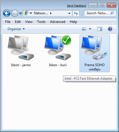
For each method of networking is made 'power profile' and when connecting to the network can choose only one of them. Method of selecting the created profile is displayed in Figure 4.5.49b example. Profiles are shown for connecting to the network, the network connection is displayed as in Figures 4.5.49c, 4.5.24a and 4.5.49d. Peculiarities that allows to connect these images are not visible but are identifiable by the initial icon showing connection type (home, office building and a bench). In previous descriptions networking networking parameters are shown in one of the ' B ' and ' C ' class without sharing class subnet procedure called 'subnetting'. Subnetting allows network traffic classification based on the settings entered into the computer for the network card, increasing the control network traffic and network security by consolidating computers into separate logical groups.
In order for two computers communicate on the same network must have different names, belong to the same group-domain (Figure 4.5.20c) and have a properly configured firewall and the sharing of resources. IP address can be obtained automatically from SOHO gateway device or via APIPA mechanism. APIPA mechanism allows the computer to communicate on the network is automatically generated by the DHCP settings if the server is unavailable. Computer's IP address and the IP address of the gateway device does not have to be in the same network. According to the above, the following example shows how a private network class ' C ' to use undivided or divided into two parts.
Example I
For home network use private network ' C ' class 192.168.128.0 which has the possibility of addressing 254 computers and devices. Two computers in the network to have a static address: 192.168.128.3 and 192,168,128,133. Computers have a common output to the Internet at the address 192.168.128.1 (gateway), which is basically the entrance to the router that transforms public address <=> private with NAT mechanism. The first IP address in the network is commonly used for this purpose. So, if the account off IP router for the computer and other devices (such as a network printer, etc.) are available 253 IP addresses.
Given network belongs to a Network Masks (NM) - 255.255.255.0. Netmask (NM) decide which network is an IP address that is assigned to your computer in a way that between the bits IP and NM perform logical AND operation. To achieve all that is understandable computer's IP address and network mask should be displayed in binary:
11000000.10101000.10000000.00000011 = 192.168.128.3    (IP of PC 1.)
11000000.10101000.10000000.10000101 = 192.168.128.133  (IP of PC 2.)
                AND
11111111.11111111.11111111.00000000 = 255.255.255.0    (Netmask)
-------------------------------------------------------------------------
11000000.10101000.10000000.00000000 = 192.168.128.0    (IP of network)
11000000.10101000.10000000.11111111 = 192.168.128.255  (IP for broadcast)
Available IP addresses for PCs      = 192.168.128.2
                                           :     .
                                      192.168.128.254
For these networks can also be used in the description of the CIDR (Classless Inter-Domain Routing) notification in the format 'IP_NETWORK_ADDRESS / 24' in order to know exactly how many bits of the address complete participates in the network address. Since computers are advertised in the example in the same network, each other 'see'. Condition that they would exchange information that must belong to the same GROUP and that they must have different NAMES.
Example II
For home network use private network ' C ' class 192.168.128.0 to be divided into two subnetworks each of which shall have the option of addressing 126 computers and devices. Two computers on the network to have a static address: 192.168.128.3 and 192,168,128,133, each in its subnet to one another 'no see'. Computers have a common output to the Internet at the address 192.168.128.1 (gateway), which is basically the entrance to the router that transforms public address <=> private with NAT mechanism.
If the leading bit of last octet of Network Masks (NM), separated from the remains of octets with a ' ' ' in order to facilitate understanding of logical operations, convert to the ' 1 ' then gets the following configuration:
11000000.10101000.10000000.0'0000011 = 192.168.128.3    (IP of PC 1.)
11000000.10101000.10000000.1'0000101 = 192.168.128.133  (IP of PC 2.)
                AND
11111111.11111111.11111111.1'0000000 = 255.255.255.128  (NM)
-----------------------------------------------------------------------------
11000000.10101000.10000000.0'0000000 = 192.168.128.0    (IP of subnetwork 1.)
11000000.10101000.10000000.0'1111111 = 192.168.128.127  (IP for broadcast 2.)
Available IP addresses for PCs       = 192.168.128.2
                                            :     .
                                       192.168.128.126

11000000.10101000.10000000.1'0000000 = 192.168.128.128  (IP of subnetwork 2.)
11000000.10101000.10000000.1'1111111 = 192.168.128.255  (IP for broadcast 2.)
Available IP addresses for PCs       = 192.168.128.129
                                            :     .
                                       192.168.128.254
For these networks can be used and a description of the format 'IP_NETWORK_ADDRESS / 25' in order to know exactly how many bits of the address complete participates in the network address. Each of the configurations shown in the examples have the last IP address in the network (subnet) is reserved for advertising on a computer register their presence at the time of start-up and during operation. Dividing the network into smaller networks - subnet within a larger network, reduce the amount of advertising within each subnet. Since computers are advertised in each case in its subnet, each not 'see'. They need not be in the same GROUP but must have different NAMES.
Smallest networks, no additional subnets, called the broadcast domain in which the computer and network devices communicate with each other directly, using the physical (MAC) addresses. The purpose of dividing the network into smaller pieces of advertising is reduced, which means less of the total traffic and 'talks' between computers in a network. The greater the number of computers in the domain, there are more advertising and can lead to unwanted domestic traffic congestion. Distribution of computers in newsgroups can also be one of the reasons for dividing the network into subnets, with giving you more security, especially if the sharing network using VLAN technology and banning traffic between subnets.
Example of division network (subletting) Class 'B' in the subnet class 'C' is shown in the example Chapter 4.4.4.. These examples relate to the division of the network into smaller parts on the 'boundary' (classfull), while 'Example II' on this page to divide a network out 'boundaries' (classless).
According to descriptions of the icons according to Figures 4.5.92a and 45.91b shows that each method of connection may be to the liking of the user name. The first two icons related to the configuration of the ISP (PPPoE protocol regarding authorizations) and TCP / IP settings in this chapter should be left to automatically set via DHCP services ISP, as shown in Figures 4.5.92c and 45.91d. The network card, related to the internal connection and the connection with the router and set the Figure 4.5.93a; they can be automatically downloaded via a DHCP router to Figure 4.5.93b and then all the computers in a private network where the and a router, or a network established by the scheme, according to figures 4.5.93c and 4.5.93d describing 'EXAMPLE II'. The router provides NAT mechanism to connect to the Internet in both cases.

|

| |
| Figure*** 4.5.92 Dynamic IP addresses. | ( + / - ) | Figure*** 4.5.93 Subnet static IP address. |
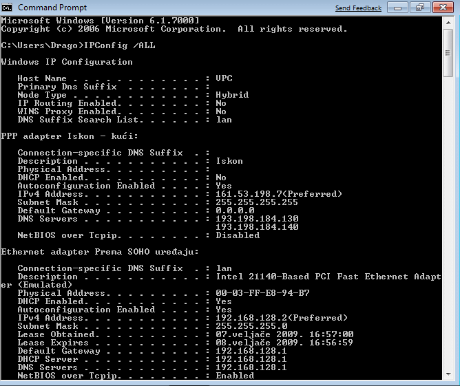
If each computer has a static IP addresses on the network router (network 192.168.128.0 with network mask 255.255.255.0), the router automatically recognizes them and used them for new computer added to the network. Thus, the computer can be on the same network (network 192.168.128.0 with network mask 255.255.255.0), as in 'EXAMPLE I', or in different subnets as in 'EXAMPLE II' (subnet 192.168.128.0 and 192.168.128.128 with network mask 255.255.255.128) and are set according to Figures and 4.5.93c 4.5.93d which proves that DHCP mechanism is inactive. In both cases, the IP addresses that refer to the same access router (gateway and DNS); other preferences 'internal' private networks can be adjusted to fit. Changes to the network settings for the described examples illustrate prints by command 'IPConfig /ALL' according to the following set of images.

|
| Figure** 4.5.94 Reading computer network settings - DHCP / Subnet. ( + / - ) |
Router, if you have this peculiarity, it recognizes static address assigned to a computer and do not use the DHCP allocation process parameters pasted to the new computers in the network if the planned static IP addresses of computers belonging to his network. If the planned static IP address of your computer are on the same network in which the router, newly added to the computer in the network will not be 'seen' by the existing computer if the IP address obtained through DHCP mechanism by router, because the planned network, along with different Router . Therefore, when you add a new computer to the network on the above should be taken into account. Stated only makes sense if there is a need to communicate via computer static IP addresses and are divided into separate groups (subnet) for security reasons.
For daily work in the home network is enough to automatically set the IP address via DHCP services SOHO router. Setting your computer is carried out according to Figure 4.5.93b, DHCP mechanism when connecting a computer to a network computer assigns the first available IP address and the configuration can be sensed in the image 4.5.94a, which shows that the first found free IP address 192.168.128.2. 'PUBLIC' facilities made available via the computer NAME in group homes. In case you need a device that has a static IP address, it should be planned within the network routers. On the set of configuration files 4.5.94 printed clearly show the differences in the segments 'computer (Ethernet Adapter) - router' and 'router - ISP (PPP adapter)', which is vividly seen as 'connecting line' on the set of files 4.5.49. According to Figure 4.5.93b shows that are available and the card ||Alternate Configuration||, which is used to tune the parameters in it that will be accepted if nothing was found or offered the option ||General|| and DHCP mechanism (similar to the settings according to the animated Figure 4.4.38b). Cards ||Alternate Configuration|| if there is no default IP address by entering the appropriate data. So, using DHCP mechanism can define two commonly used configurations.
Descriptions of this party are primarily related to the home and public network connections. Connections in the business environment is much simpler to configure network parameters only Ethernet card to the address scheme established by the company regarding the benefits of networking. Caring about other network devices and LAN servers. Figure 4.5.95a shows how the server business local area networks (gem.ktf) embraced the computer upon completion of the process of installing the operating system and immediately realized that there is no possibility of connection interruption and re-establishing connections as shown in Figure 4.5.49b. How are installing the operating system does not require adjusting network parameters, the computer picks them from the server ('gem.ktf' in the example) using its DHCP service from the default settings to 4.5.95b, which are read by choice /Change adapter settings/ with pictures 4.5.95a. Static network address scheme adopted by local business networks are subsequently awarded.

|
| Figure* 4.5.95 Network settings of computer in LAN. ( + / - ) |
The above pictures were 'aero' windows operating system that are identified by the semi transparent frames and window header.
The main difference in the display connectivity in the LAN environment and home (broadband) environment can be seen immediately after presentation of the 'View your active networks', which according to the above figure for the local business network is a group of content immediately available and complete 'interconnection line' while home connectivity non-established when communication has broken 'interconnection line' as shown 4.5.49a, and by establishing communication display changes to Figure 4.5.49c which now contains a complete 'interconnection line' and one more row of icons in the 'View your active networks' content (picture of bench). LAN connection (gem.ktf) no button for the exercise and disconnect as 'Broadband Connection', as can be seen in a small window on the right side of the picture. Interrupt LAN connection is done off computer from the network cable or disconnecting choice /Disable/ properties in network card.
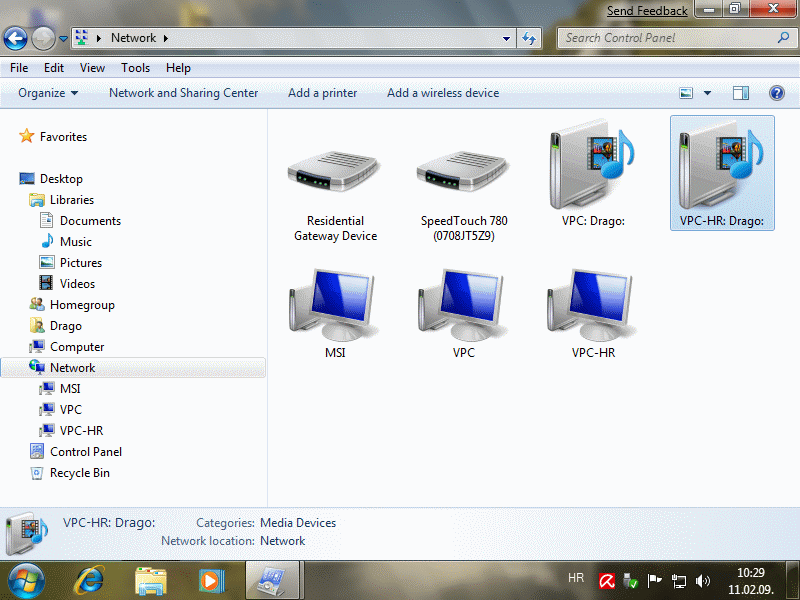
Figure 4.5.96a shows to see all the devices that are available in the home network, you can make out the two virtual PC (VPC and VPC-HR), their 'rights' to the host computer (MSI) and network device that achieves connectivity with ISP (SpeedTouch), and it also shows that VPC computer from which members reviewed a home network can have 'aero' characteristics, if the recorded views 'scarecrow' in image processing :-).

|
| Figure* 4.5.96 Members of the computer network. ( + / - ) |
The picture shows that they are available and multimedia devices, but in essence it is about putting the availability of multimedia content on the computer in the network and their handling by all participants in the network. If you carefully read their detailed description can be seen that the one available over the network and the other is on the computer (Network location:). Way of putting the device and files available to members of the network are described on the following page. Menu for monitoring network connectivity (small window on the right side of Figure 4.5.96b) shows clearly the local and Internet connectivity of the Internet connection which can be turned off without affecting the availability of resources within the home network.
According to the above examples, it is clear that the network card can be configured to work only in a single network, and not for the simultaneous operation of multiple networks, regardless of the protocol used in the work. The above noted in previous chapters. An example of networking computers and devices with static and dynamic IP addresses in a private network of SOHO environment is shown in Figure 4.4.14.
|
Citing of this page: Radic, Drago. " Informatics Alphabet " Split-Croatia. {Date of access}; https://informatics.buzdo.com/file. Copyright © by Drago Radic. All rights reserved. | Disclaimer |